![]()
Installing the Hot-Spark Electronic Ignition Conversion Kits and Distributors
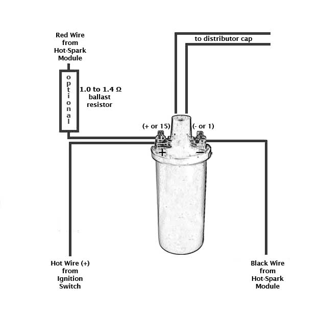
Test Maximum Charging System Voltage: If the charging system voltage, measured at the coil’s positive terminal, is more than 13.9 volts at any RPM level, the voltage regulator likely needs replacing. Too much voltage can destroy the ignition module and other electronic components. A maximum charging system voltage of 13.5 volts or so is plenty. A quick fix is to wire a 1.7 Ohm external ballast resistor between the coil's + terminal and the HotSpark ignition's red wire. Adding the ballast resistor is cheap insurance against voltage surges, etc.
Latest On-Line Electronic Ignition Conversion Kit Installation Instructions:
www.Hot-Spark.com/Installing-Hot-Spark.htm
Coil Required: Do not use a low-resistance coil that does not have the minimum primary resistance required by the ignition module, as stated in the instructions (minimum 3.0 ohms, assuming a 12-Volt electrical system). The coil resistance regulates the current in the ignition module/coil circuit. Too little coil primary resistance resistance results in too much amperage going to the ignition module, which can overheat the electronics. The failure may not happen immediately, but the excess heat will shorten the life of the ignition module electronics. How long the electronics will last depends on how much heat is generated. It could be a matter of a couple of hours to a few hundred hours, depending on temperature.
To measure coil primary resistance: Label and remove all wires to coil (
+ or - ). Using a common digital multimeter in the 200 Ω mode, cross the red and
black leads of the Ohmmeter. Allow 10 seconds or so for the reading to settle
and then write down the reading. Still in the 200 Ohm mode, measure between coil’s +
and - terminals. Allow a few seconds for the reading to settle, until it
stabilizes. Subtract the previous reading, taken with the leads crossed, to
compensate for Ohmmeter’s inherent resistance. Do not use a low-resistance coil,
such as the MSD or Accel coil; they don’t have enough primary resistance for
this application. For best performance, the coil should also have 7,000 Ohms or
more secondary resistance (measured from coil’s + or – terminal to center high
tension terminal, in the 20K Ω mode of the Ohmmeter).
Test the charging system's maximum voltage: 8-Cylinder: Check the voltage reading at the coil's + terminal, engine running. If the voltage measures more than +13.9 volts, at any RPM level, you'll need to replace the voltage regulator, install a coil with 1.5 Ohms or more internal primary resistance and/or install a 1.7 Ohm external ballast resistor between the coil's + terminal and the Hot Spark ignition's red wire. Adding the ballast resistor is cheap insurance against voltage surges, etc.
Included with most ignition kits: A packet of white thermal transfer paste. Clean distributor's breaker plate spotlessly clean. Apply a uniform, thin layer of the included packet of white thermal paste to bottom of ignition module to ensure better cooling of ignition module.
Many distributors have distributor shafts that may vary in height, depending on the wear, number and thickness of the distributor shaft shims inside the distributor and/or above the distributor's drive gear. If there's more than 0.8 mm (1/32 of an inch) of up-and-down play in the shaft, you'll likely need to adjust the number and thickness of the shims.
A small O-Ring may have been provided to raise the height of the magnet sleeve,
if that is necessary. If needed, install the O-Ring around the distributor
shaft, underneath the magnet sleeve, to boost magnet sleeve height.
Plug Wires
Wiring Installation Basics:
1. Begin with a fully-charged battery. Turn on the ignition switch. With engine
not running, using a voltmeter in the 20 Volt DC mode, check that the voltage,
measured at the coil's + terminal, is around +12.5 volts, about the same as
battery voltage. The red voltmeter lead should touch the coil's + terminal while
the black voltmeter lead is touching engine ground. If voltage reading is too
low or there’s no reading, the battery’s terminals or ground connection may be
corroded and need cleaning. Some vehicles have a resistor wire running from the
ignition switch to the coil’s + terminal. If this resistor wire drops the
voltage below 11 volts or so, you may need to run a non-resistor wire from the
ignition switch to the coil’s + terminal or run a +12V wire directly from the
ignition switch to the red Hot-Spark ignition wire. Make sure that the ignition
switch terminal to which you connect this wire has power only when the ignition
switch is in the ON position.
Or, you can, for temporary testing purposes only, run a wire directly from the
battery's + terminal to the Hot Spark ignition's red wire and the black Hot-Spark wire to the coil's - terminal.
Do not leave the wire from the battery connected to the ignition module's red
wire for
more than a minute or so without the engine running.
2. Remove the points, condenser and the condenser's wire from the vehicle.
To get the ignition running initially, only these wires should be attached to
the coil's + and - terminals:
A. +12 volts from the ignition switch (+12-volt power source) to the coil's +
terminal
B. Red Hot-Spark wire to the coil's
+ terminal
C. Black Hot-Spark wire to the coil's - terminal. DO NOT connect any +12-volt wire to the coil's - terminal. Connect only the
black Hot-Spark ignition wire to the coil's - terminal. Do not connect the coil's - terminal
to ground (earth). It will act like a kill switch and the engine cannot run.
D. The automatic choke and fuel shut-off valve may also need to be attached to
the coil's + terminal.
E. Generally, only the black Hot-Spark wire is attached to the coil's -
terminal. If a tachometer wire is usually attached to the coil's - terminal,
don't attach it until the timing has been set and engine is running properly. No
other wires should be connected to the coil's + and - terminals at this time.
F. Attach a stroboscopic timing light to the spark plug wire of Cylinder number
1. With engine rotated to TDC (0 degrees) on the firing stroke of Cylinder
number 1, ignition switch ON, turn the distributor until the timing light
flashes. Tighten the distributor clamp enough so that the distributor won't turn
on its own. Start the engine. You may need to turn the distributor left or right a
little, a little at a time, until the engine will stay running, so that you can
set the timing with the engine running, using a stroboscopic timing light,
according to factory specifications.
Set
the ignition timing, with a stroboscopic light, to the distributor’s factory
specification. The difference in distributor position with points vs. electronic
ignition, depending on the distributor, can be as much as 30 degrees or so clockwise or counterclockwise, so
you’ll definitely have to reset the timing, using a stroboscopic timing light. The old method of setting the
timing statically, using a simple 12-volt test lamp, won't work with
electronic ignition, as it does with points. The only way to bench-test an electronic
distributor is by using a distributor testing machine. In other words, the
distributor needs to be mounted in the engine and tested and/or timed using a
stroboscopic timing light, connected to number one cylinder's spark plug wire.
G. For testing purposes, no other wires should be attached to the coil
terminals, except for the center high-tension lead to the distributor cap.
Latest On-Line Electronic Ignition Conversion Kit Installation Instructions:
Bosch Distributors: www.Hot-Spark.com/Installing-Hot-Spark-Bosch.htm
Volvo-Penta (Bosch) Distributors: www.Hot-Spark.com/Installing-Hot-Spark-Volvo-Penta.htm
Ford (non-Bosch) Distributors (3FOR4V3, 3FOR6U1, 3FOR8U1): www.Hot-Spark.com/Installing-Hot-Spark-Ford.htm
Delco Distributors (3DEL4U1, 3DEL6U1): https://www.Hot-Spark.com/Installing-Hot-Spark-Delco.htm
Ducellier Distributors (3DUC4U1): www.Hot-Spark.com/Installing-Hot-Spark-Ducellier.htm
Hitachi Distributors (3HIT4U1): www.Hot-Spark.com/Installing-Hot-Spark-Hitachi.htm
Hitachi HS-HIT4 Distributor Installation Instructions: www.Hot-Spark.com/Installing-HS-HIT4-Distributor.htm
Lucas Distributors (3LUC4-25D, 3LUC4-45D, 3LUC6-22D, 3LUC8-35D): www.Hot-Spark.com/Installing-Hot-Spark-Lucas.htm
Mallory 8-cylinder Marine Distributor: (3MAL8U1): www.Hot-Spark.com/Installing-Hot-Spark-Mallory.htm
Nippondenso Distributors (3ND4U1, 3ND6U1): www.Hot-Spark.com/Installing-Hot-Spark-Nippondenso.htm
Prestolite Distributors (3PRE8U1, 3PRE8U2, 3PRE6U2): https://www.Hot-Spark.com/Installing-Hot-Spark-Prestolite.htm
Autolite Distributors (3AUT4U1, 3AUT4U2, 3AUT6U1, 3AUT6U2): https://www.Hot-Spark.com/Installing-Hot-Spark-Autolite.htm
Installing SVDA 034 Distributor (also Bosch SVDA 034): www.Hot-Spark.com/Installing-SVDA-034.htm
Installing 009 Distributor: www.Hot-Spark.com/Installing-009-3BOS4U1.htm
Installing HS25D4 or HS45D4 (Lucas) 4-Cyl Distributor: www.Hot-Spark.com/Installing-HS45D4-Distributor.htm
Coil Required: Do not use a low-resistance coil that does not have the minimum primary resistance required by the ignition module, as stated in the instructions (4- 0r 6-cyl: (minimum 3.0 ohms, assuming a 12-Volt electrical system). 8-cyl: Coil with minimum of 1.5 Ohms primary resistance.
The coil resistance regulates the current in the ignition module/coil circuit. Too little coil primary resistance resistance results in too much amperage going to the ignition module, which can overheat the electronics. The failure may not happen immediately, but the excess heat will shorten the life of the ignition module electronics. How long the electronics will last depends on how much heat is generated. It could be a matter of a couple of hours to a few hundred hours, depending on temperature.
To measure coil primary resistance: Label and remove all wires to coil ( + or - ). Using a common digital multimeter in the 200 Ohm mode, cross the red and black leads of the Ohmmeter. Allow 10 seconds or more for the reading to settle and write down the reading. Still in the 200 Ohm mode, measure between coil’s + and - terminals. Allow a few seconds for the reading to settle, until it stabilizes. Subtract the previous reading, taken with the leads crossed, to compensate for Ohmmeter’s inherent resistance. Do not use a low-resistance coil, such as the MSD or Accel coil; they don’t have enough primary resistance for this application.
For best performance, the coil should also have 7,000 Ohms or more secondary resistance (measured from coil’s + or – terminal to center high tension terminal, in the 20K Ω mode of the Ohmmeter). Ballast Resistor: If the coil's primary resistance is borderline, you can wire an external ceramic ballast resistor (with 1.4 Ohms resistance) between the coil's + terminal and the red HotSpark ignition wire:
www.Hot-Spark.com/1-HS17BR.htm
Test the charging system's maximum voltage: Check the voltage reading at the coil's + terminal, engine running. If the voltage measures more than +13.7 volts, at any RPM level, you'll need to replace the voltage regulator, install a coil with 3.0 Ohms or more internal primary resistance and/or install a 1.4 to 1.7 Ohm external ballast resistor between the coil's + terminal and the Hot Spark ignition's red wire.
Included with most ignition kits: A packet of white thermal transfer paste. Clean distributor's breaker plate spotlessly clean. Apply a thin, uniform layer of the included packet of white thermal paste to bottom of ignition module to ensure better cooling of ignition module. Many distributors have distributor shafts that may vary in height, depending on the wear, number and thickness of the distributor shaft shims inside the distributor. A small crescent-shaped plate and metric hex-head screws may have been included with the ignition kit in case you need to boost the height of the red ignition module to align with the magnets inside the magnet sleeve. A small O-Ring may have been provided to raise the height of the magnet sleeve, if that is needed instead. Install the O-Ring around the distributor shaft, underneath the magnet sleeve.
Plug Wires Stock copper-core plug wires are usually OK to use with the Hot Spark ignition. If you're buying new spark plug wires, we suggest using carbon core, spiral-wound, stainless steel spark plug wires.
Hot-Spark Ignition and MSD 6 Series Wiring Diagram: www.Hot-Spark.com/Hot-Spark-MSD-6-Series.jpg
Troubleshooting/FAQ: Having installation problems? Click here
Email Us: info@Hot-Spark.com
© 2005-2025 Hot Spark®