
Installing the Hot-Spark SVDA 034 Distributor with 3BOS4U1 Electronic Ignition
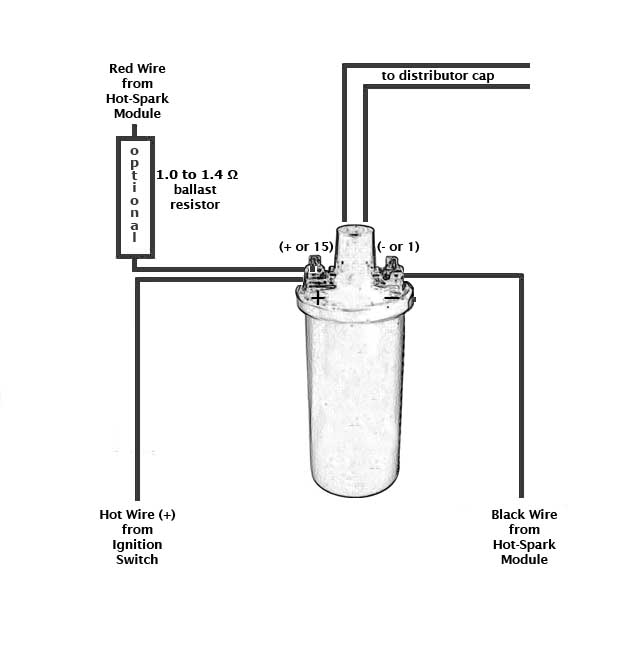
Warning: Reversing the red and black ignition wires will destroy the ignition module. The Hot-Spark module’s red wire connects to positive ( + or 15 on Bosch coil). The black wire connects to negative ( – or 1 on Bosch coil). Connect any other wires to the coil in their original positions. This module is designed for 12V negative ground applications only.
Test Maximum Charging System Voltage: If the charging system voltage, measured at the coil’s positive terminal, is more than 13.9 volts at any RPM level, the voltage regulator likely needs replacing. Too much voltage can destroy the ignition module and other electronic components. A maximum charging system voltage of 13.0 volts or so is plenty. A quick fix is to wire a 1.7 Ohm external ballast resistor between the coil's + terminal and the HotSpark ignition's red wire. Adding the ballast resistor is cheap insurance against voltage surges, etc.
Make sure that the ignition wires have plenty of slack inside the distributor and are not rubbing on any moving parts. If you need to extend the length of the ignition wires, use 20-gauge (AWG) wire. Crimp tightly or solder all connections.
For proper operation of the distributor's vacuum advance, the vacuum source needs to be able to generate a minimum of about 8 inches (200 mm) of Hg. If your engine is running a high-lift, long duration cam, with cam overlap or an aftermarket carburetor setup without an available vacuum source, the vacuum-advance mechanism may not advance fully. However, the distributor's centrifugal-advance mechanism will provide the same advance curve as a properly set-up 009 centrifugal-advance distributor, simply by capping off the vacuum port.
Coil:
4-Cylinder: Coil must have a minimum of 3 Ohms primary resistance. To measure primary
resistance: Label and remove all wires to coil ( + or - ). Using a common
digital multimeter in the 200 Ω mode, cross the red and black leads of the
Ohmmeter. Allow a few seconds for the reading to settle and write down the
reading.
Still in the 200 Ohm mode, measure between coil’s + and - terminals. Allow a few
seconds for the reading to settle, until it stabilizes. Subtract the previous
reading, taken with the leads crossed, to compensate for multimeter’s inherent
resistance. Do not use a low-resistance coil, such as the MSD or Accel coil;
they don’t have enough primary resistance for this application.
Using a coil with too little primary resistance can cause
the ignition module to overheat and misfire until it cools down again or fail,
voiding the warranty.
Check the voltage reading at the coil's + terminal, engine running, at 2,500+
RPM. If the voltage measures more than +13.9 volts, you'll need to replace the
voltage regulator, install a coil with 3 Ohms or more internal primary
resistance and/or install a 1.4 Ohm external ballast resistor between the coil's + terminal
and the red Hot Spark module's red wire. Adding the ballast resistor is cheap insurance
against voltage surges, etc.
For best performance, the coil should also have 7,000 Ohms or more secondary resistance (measured from coil’s + or – terminal to center high tension terminal, in the 20K Ω mode of the Ohmmeter).
Test Battery Voltage to Coil: With ignition switch ON, engine not running, check voltage at coil’s + terminal. The voltmeter should read somewhere around +11 to +13 volts. If voltage is too low or there’s no reading, the battery’s terminals or ground connection may be corroded and need cleaning or the battery may need charging. Some vehicles have a resistor wire running from the ignition switch to the coil’s + terminal. If this resistor wire drops the voltage below 9 volts or so, you may need to run a non-resistor wire from the ignition switch to the coil’s + terminal or run a +12V wire directly from the ignition switch to the red Hot Spark ignition wire. Make sure that the ignition switch terminal to which you connect this wire has power only when the ignition switch is in the ON position. Or, you can, for temporary testing purposes only, run a wire directly from the battery's + terminal to the coil's + terminal, the Hot Spark ignition's red wire to the coil's + terminal and the black Hot-Spark wire to the coil's - terminal. Do not leave the wire from the battery connected to the coil's + terminal for more than a minute or so without the engine running.
Can use these standard Bosch replacement parts:
Compatible Carburetors: The following carburetors should produce the proper amount of vacuum for use with the SVDA 034 distributor (if they are fitted with a vacuum port):
If your car has Kadron or ICT carbs, connect the vacuum hose to at least one carburetor. If your car has dual IDF or DRLA carbs, run a vacuum hose to both carburetors, "T" them together and then run the vacuum hose to the SVDA 034's vacuum port.
If your '71 VW Bus or '71-'74 VW Beetle/Ghia/Thing has the original dual-vacuum distributor and you replace it with the SVDA 034, you'll need to plug (cap off) the carburetor's retard vacuum port, which is the port located closest to you as you're looking at the carburetor from the rear of the car. Use the advance vacuum port, located on the left side of the 34PICT carburetor.
This distributor requires a 12-volt, negative ground electrical system.
Make sure that engine oil level is on the full mark before revving engine!
Finding Top Dead Center on a VW Type I engine: https://www.vw-resource.com/find_tdc.html#pulley
Which is Number One Cylinder?
You can rotate the position of the spark plug leads in the distributor cap, as needed, so that the arrangement of the ignition wires and the position of the vacuum canister best suits your particular application. Any of the distributor cap’s four spark plug wire positions can be for number one cylinder, as long as the firing order remains 1-4-3-2, clockwise. Cylinder number 1 for Type I VW engines is normally at about the eleven o'clock position, when looking down on the engine from above. For VW Type IV engines (1972-83 USA VW bus), Cylinder No. 1 is normally at about the five o'clock position. Each cylinder firing position is 90° from the next or last, including Cylinder number 3 (No. 3 is not retarded).
Lubricating Distributor
Occasionally lubricate the distributor shaft and its bushing and the swinging centrifugal advance weights in the bottom of the distributor. A small amount of heavy oil, such as 90W hypoid, synthetic heavy transmission oil or heavy motor oil works well for lubricating the distributor. Don't use a thin solvent, such as WD-40, for lubrication, as its lubricating qualities won't last for long. Clean up any excess oil or grease.
Installing Distributor in VW Type I Engine - Beetle, Ghia, Thing, 1950-71 Bus (USA)
Before removing the old distributor, rotate the crankshaft to TDC (0°) on the compression stroke for Cylinder number 1. You can locate Cylinder number 1's firing position like this:
Remove the right-side valve cover, exposing the valves of Cylinders number 1 and 2 (Cylinder 1 is closest to the front of the car). The exhaust valves for Cylinders number 1 and 2 are closest to the front and rear of the car, respectively (on the outside). Cylinders number 1 and 2 intake valves are next to each other (on the inside). Rotate the engine clockwise, by hand, until you see Number 1 cylinder's exhaust valve open. Keep rotating the engine until the intake valve opens and then closes. Turn the engine by hand, clockwise, until the TDC (0°) notch in the crankshaft pulley wheel is lined up with where the two engine case halves join. The Woodruff key that fastens the pulley to the crankshaft should be at the nine o'clock position. The old distributor's rotor should be pointed to Cylinder number 1's spark plug wire. That is TDC (0°) on the compression stroke for Cylinder number 1.
Another method of finding Cylinder number 1's compression stroke is by removing the spark plug from Cylinder number 1, and holding your finger or thumb over the empty spark plug socket. Turn the crankshaft pulley clockwise, by hand, until you can feel compressed air rushing from spark plug hole (it's then on the compression stroke). Turn the pulley a little, until the TDC (0°) notch lines up with where the two engine case halves join or the crankshaft pulley's Woodruff key is at the nine o'clock position. The rotor should be pointing at the spark plug wire for Cylinder number 1.
The air-cooled VW's cylinders are arranged as follows:
Front of Car
3 1
4 2
Rear of Car
As you look at the exhaust and intake valves from the car's right side:
Cylinder 2 Cylinder 1
Exhaust Intake Intake Exhaust
The rotor should be pointing to No. 1 Cylinder's spark plug wire. Note the location of the tab on the rim of the distributor cap and orient it so that it aligns with the notch in the rim of the old distributor's body. Remove each spark plug wire from the old distributor cap, one-at-a-time, and insert it into the new distributor cap in the same location and order (cylinders 1-4-3-2, clockwise).
Remove the old distributor and remove its clamp. Slide the distributor clamp onto the new distributor, before you fit the O-Ring to the distributor shaft. Now slide the O-Ring onto the distributor shaft and into its groove. Coat the distributor shaft and O-Ring with motor oil before sliding it into its hole. Look down into the engine's distributor hole to see how the distributor drive slot is oriented and turn the distributor shaft to match it. Make sure that the anti-chatter spring is in place, down in the center of the hole. Insert the distributor shaft into the hole. You might need to tap the distributor's rim gently to get the O-Ring started into the hole. Work the shaft down all the way, turning the rotor gently, as needed, until the distributor shaft gear settles into its slot and the rotor will no longer turn.
Place the cap on the new distributor. The rotor should point to Cylinder number 1. If not, move the spark plug wires in the distributor cap around, until the rotor points to the spark plug wire for Cylinder number 1. Cylinders 4, 3 and 2 spark plug wires should follow, in a clockwise direction (1-4-3-2 firing order).
If the rotor doesn't point to number 1 cylinder, the distributor drive pinion may be installed incorrectly. It will need to be removed from the distributor shaft hole with a special extraction tool and reinstalled so that its slot is oriented correctly (see VW repair manual for illustration).
Timing the SVDA 034 Distributor
TDC = Top Dead Center, or 0° BTDC = Before Top Dead Center ATDC = After Top Dead Center
34PICT Carburetor: Use the vacuum port on the LEFT side of the 34PICT carburetor (advance port). Use vacuum hose with an inside diameter of 4mm.
You can locate the 30° BTDC spot on a stock VW Type I crankshaft pulley, which has a 175 mm (6-7/8 in.) diameter, by measuring, clockwise, from top dead center, around the circumference of the pulley, 45.8 mm, or 1-13/16 in. Make a small white paint mark there. That's about 30° BTDC.
Connect the hose from the vacuum source to the distributor's vacuum canister. The vacuum source is normally the carburetor body or the fuel injection's throttle body. For proper operation of the distributor's vacuum advance, the vacuum source needs to generate a minimum of 8 inches (200mm) of Hg. If the distributor you're replacing is a dual-vacuum-advance model, cap off the larger retard vacuum port of the carburetor, and connect the vacuum hose from the left side of the carburetor only (Solex 30- or 34-PICT carburetor).
After you connect the vacuum hose, timing should be about 40-42° BTDC at full advance (vacuum hose connected, no load on engine, 3,500+ RPM).
You can locate the 42° BTDC spot on a stock VW Type I crankshaft pulley, which has a 175 mm (6-7/8 in.) diameter, by measuring, clockwise, from top dead center, around the circumference of the pulley, about 64 mm, or 2.52 in. Make a small white paint mark there. That's about 42° BTDC.
Click here for printable VW Type I crankshaft pulley degree template for SVDA 034 distributor.
See www.Hot-Spark.com/Installing-Hot-Spark.htm for more detailed information.
Vacuum Hose: The outside diameter of a VW/Solex carburetor's vacuum port is 4.4mm. Vacuum hose with an inside diameter of 4mm is normally used to connect the carburetor's vacuum port and the distributor's vacuum canister.
Wiring Installation Basics:
1. Remove points, condenser and condenser wire from the vehicle.
2. Attach the red lead of a voltmeter to the coil's positive ( + or 15) terminal. Attach the voltmeter's black lead to engine ground. With the ignition switch on, engine not running, measure the voltage at the coil's positive ( + or 15) terminal. The reading should be somewhere around +11 to +13 volts. If voltage is too low or there’s no reading, the battery’s terminals or ground connection may be corroded and need cleaning. Some vehicles have a resistor wire running from the ignition switch to the coil’s + terminal. If this resistor wire drops the voltage below 9 volts or so, you may need to run a non-resistor wire from the ignition switch to the coil’s + terminal or run a +12V wire directly from the ignition switch to the red Hot-Spark ignition wire. Make sure that the ignition switch terminal to which you connect this wire has power only when the ignition switch is in the ON position.
To get the ignition
running initially, only these wires should be attached to the coil's + (15) and
- (1) terminals:
A. +12 volts from the ignition switch to the coil's + terminal
B. Red Hot-Spark wire to the coil's + terminal
C. Black Hot-Spark wire to the coil's - terminal. DO
NOT connect any +12-volt wire to the coil's - terminal. Connect only the
black Hot-Spark ignition wire to the coil's - terminal.
D. The automatic choke and fuel shut-off valve may also need to be
attached to the coil's + terminal.
E. Generally, only the black Hot-Spark wire is attached to the coil's -
terminal. If a tachometer wire is usually attached to the coil's - terminal,
don't attach it until the timing has been set and engine is running properly. No
other wires should be connected to the coil's + and - terminals at this time.
F. Static timing, using an ordinary 12-volt test lamp, will not work, as with points. Attach a stroboscopic timing light to the spark plug wire of Cylinder number 1. With engine rotated to 7.5° BTDC, on the firing stroke of Cylinder number 1, ignition switch ON, turn the distributor until the stroboscopic timing light flashes. Tighten the distributor clamp a little, so that you can still turn the distributor by hand, but the distributor won't turn on its own. You may need to turn the distributor left or right, a little at a time, until the engine will stay running, so that you can set the timing with the engine running, using a stroboscopic timing light.
G. For testing purposes, no other wires should be attached to the coil
terminals, except for the center high-tension lead to the distributor cap.
The rotor should be pointing to number 1 cylinder's spark plug wire. The position of the rotor will be different than the position of a 009 (which is non-standard) distributor's rotor. If necessary, you can rotate the wires, as long as the firing order remains the same: 1-4-3-2, clockwise.
Start the engine. You may need to turn the distributor left or right a little, until the engine will stay running, so that you can set the timing with the engine running, using a stroboscopic timing light. With vacuum hose disconnected and plugged, the timing should be set to 30-32 degrees BTDC at 3,500+ RPM. With the vacuum hose connected, timing should not exceed 42-44 degrees BTDC at 3,500+ RPM.
Using Hot-Spark Ignition with VDO Tachometer: Connect a diode #1N4005 between the negative terminal (- or 1) of the coil and the wire that goes to the tachometer. The cathode end (silver band) should be nearest the tachometer side, not the coil side. You should be able to buy a diode at an electronic supply store.
Hot-Spark Ignition and MSD 6 Series Wiring Diagram: https://www.Hot-Spark.com/Hot-Spark-MSD-6-Series.jpg
Troubleshooting/FAQ: Having installation problems? Click here
Email Us: info@Hot-Spark.com
© 2005-2025 Hot Spark®